Evolution of the Gas Turbine
Through the design experience developed for steam turbines
and available to gas turbines, it is not surprising that gas
generator compressors, turbines, and power-extraction
turbines bear a striking resemblance to each other and to the steam
turbine. Nor should it be surprising that the axial fl ow compressors
of today’s gas turbines resemble the reaction steam turbine with
the flow direction reversed. While many people today recognize the
similarities between steam and gas turbine components, most do not
fully appreciate the common history these two products share. History
tells us that the idea for the gas turbine and the steam turbine
were conceived simultaneously. As early as 1791, John Barber’s patent
for the steam turbine described other fl uids or gases as potential
energy sources. “John Barber invented what may be considered a
gas turbine in which gas was produced from heated coal, mixed with
air, compressed and then burnt. This produced a high speed jet that
impinged on radial blades on a turbine wheel rim.”1 John Barber’s
ideas, as well as those before him (Giovanni Branca’s impulse steam
turbine—1629, Leonardo da Vinci’s “smoke mill”—1550, and Hero of
Alexandria’s reaction steam turbine—130 BC)2 were just ideas. Even
though the gas turbines described by these early visionaries would
today be more accurately termed ‘turboexpanders’ (the source of compressed
air or gas being a by-product of a separate process), there is
no evidence that any of these ideas were ever turned into working
hardware until the late 19th Century.
For the next 90 years ideas abounded, but all attempts to produce
working hardware were unsuccessful. As Norman Davy stated in
1914, “The theory of the gas turbine was as fully grasped by Barber
at the end of the eighteenth century, and by Bresson in the beginning
of the nineteenth century, as it is by experts today. The success of the
gas turbine as a heat engine rest solely upon practical limitations.”
However, even in this period of unsuccessful attempts at producing a
working prototype, progress was still being made.
• In 1808 John Dumball envisioned a multi-stage turbine. Unfortunately
his idea consisted only of moving blades without stationary
airfoils to turn the fl ow into each succeeding stage.1,3,4
Had he realized the need for a stationary stage between each
rotating stage he would have originated the concept of an axial
flow turbine.
• In Paris in 1837, Bresson’s idea was to use a fan to drive pressurized
air into a combustion chamber. Here, the air was mixed
with fuel gas and burnt. These combustion products were cooled
by the addition of more air, and this fi nal product was used to
drive turbine blades.1,2
• In 1850, in England, Fernimough suggested a mixed steam and
gas turbine, in which air was blown through a coal grate while
water was sprayed into the hot gases. The gas and steam mixture
then acted to drive a two-bladed rotor.1
• Not until 1872 did Dr. Franz Stolze combine the ideas of Barber
and Dumball to develop the fi rst axial compressor driven by an
axial turbine.1 Due to a lack of funds, he did not build his machine
until 1900. Dr. Stolze’s design consisted of a multi-stage
axial fl ow compressor, a single combustion chamber, a multistage
axial turbine, and a regenerator utilizing exhaust gases to
heat the compressor discharge air. This unit was tested between
1900 and 1904, but never ran successfully.
It was not until 1884 with Sir Charles Parsons’ patent for a reaction
steam turbine and gas turbine, and 1888, with Charles de Laval’s
application of Giovanni Branca’s idea for an impulse steam turbine
did workable hardware emerge.1,3 In the 1895/1896 time
frame variations in the impulse turbine designs were developed by
August C. Rateau, Charles Curtis, and Dr. Zoelly. The experience
gained in the development of hardware for steam turbines was directly
transferable to gas turbines. At the end of the 19th Century
the ideas of the previous centuries were fi nally being transformed
into working hardware.
In 1903, Rene Armengaud and Charles Lemale built and successfully
tested a gas turbine using a Rateau rotary compressor and
a Curtis velocity compounded steam turbine. Armengaud and Lemale
went on to build and test several experimental gas turbines. Originally
they used a 25 HP de Laval steam turbine driven by compressed
gases from a combustion chamber, which was fed from a compressor.
The turbine and compressor ran at 4,000 rpm and, in another early
example of steam injection, temperatures were kept down by injecting
steam upstream of the turbine nozzle.1 Even at the turn of the
century turbine blade cooling was being integrated into the turbine
design as documented in 1914 by N. Davy who wrote, “In the experimental
turbine of Armengaud and Lemale the turbine wheel was a
double wheel of the Curtis type, water cooled throughout, even the
blades themselves being constructed with channels for the passage
of the water.” Out of necessity (they did not possess the metallurgy
to withstand high temperatures) these early pioneers used steam
and water injection, and internal air and water cooling to reduce the
temperature effects on the combustor, turbine nozzles, and turbine
blades.
Later Brown Boveri and Co. went on to build a 500 horsepower
gas turbine with a three-stage centrifugal compressor, each stage having
25 impellers in series. This centrifugal compressor, specifi cally
built for a gas turbine application, was modeled from a A.C. Rateau
design. It is sometimes diffi cult to separate, in retrospect, whether
these pioneers were augmenting their steam turbines with hot gas, or
their gas turbines with steam. But one thing is evident—their ideas
are still an important part of today’s gas turbine operation.
Throughout most of the fi rst half of the 20th century the development
of the gas turbine continued slowly. Advances were hampered
primarily by manufacturing capability and the availability of high
strength, high temperature resistant materials for use in compressor,
turbine, and combustor components. As a result of these limitations
compressor pressure ratios, turbine temperatures, and effi ciencies
were low. To overcome the turbine temperature limits, the injection
of steam and water to cool the combustor and turbine materials
was used extensively. As N. Davy noted in 1914, “From the purely
theoretical valuation of the cycle, the effi ciency is lowered by any
addition of steam to the gaseous fl uid, but in actual practice there
is a considerable gain in economy by so doing. Limits of temperature,
pressure, and peripheral speed, together with the ineffi ciencies
inherent in pump and turbine, reduce the effi ciency of the machine
to a degree such that the addition of steam (under the conditions of
superheat, inaugurated by its injection into the products of combustion)
is of considerable economic value. It is also a great utility in
reducing the temperature of the hot gases on the turbine wheel to a
limit compatible with the material of which the blades are made.”3
These techniques continue to be used even with today’s technology.
In 1905, the fi rst gas turbine and compressor unit built by
Brown Boveri was installed in the Marcus Hook Refi nery of the Sun
Oil Company near Philadelphia, PA,. It provided 5,300 kilowatts
(4,400 kilowatts for hot pressurized gas and 900 kilowatts for electricity)
1. Brown Boveri also constructed the fi rst electricity generating
turbine for a power station at Neuchatel in Switzerland1. This 4,000-
kilowatt turbine,which was exhibited in 1938, consisted
of an axial fl ow compressor delivering excess air at around 50 pounds
per square inch (3.5 kg/cm2) to a single combustion chamber and driving
a multi-stage reaction turbine. The excess air was used to cool the
exterior of the combustor and to heat that air for use in the turbine.
Some six years behind Whittle, Germany’s Hans Pabst von Ohain
put forth his ideas for a turbojet engine in 1935. It consisted of a compound
axial-centrifugal compressor similar to Whittle’s patent design
and a radial turbine. H.P. von Ohain’s designs were built by aircraft
manufacturer Ernst Heinkel. August 24, 1939 marked the fi rst fl ight
of a turbojet aircraft, the He 178, powered by the HeS 3B engine.
Throughout the war years various changes were made in the
design of these engines: radial and axial turbines, straight through
and reverse fl ow combustion chambers, and most notably the axial
compressor. The compressor pressure ratio, which started at 2.5:1 in
1900, went to 5:1 in 1940, 15:1 in 1960, and is currently approaching
40:1. Since the Second World War, improvements made in the aero
gas turbine-jet engine industry have been transferred to the stationary
gas turbine. Following the Korean War, the Pratt & Whitney
Aircraft designed JT3 (the military designation was the J57) provided
the cross-over from the aero gas turbine to the stationary gas turbine.
The JT3 became the FT3 aeroderivative. In 1959, Cooper Bessemer
installed the world’s fi rst base-load aeroderivative industrial gas
turbine, the FT3, in a compressor drive application for Columbia
Gulf Transmission Co. at their Clementsville, Ky., mainline compressor
station (Figure 1-3). The unit, designated the RT-246, generated
10,500 brake horsepower (BHP) driving a Cooper-Bessemer RF2B-
30 pipeline compressor.9 In 1981, that unit had accumulated over
100,000 operating hours and is still active.
Table 1-1 is a chronology of key events in the development of
the gas turbine as it evolved in conjunction with the steam turbine.
Absent from this list are an unknown number of inventors such as
John Dumball. Their contribution was not in demonstrating to the
engineering community what worked, but what did not work.
Table 1-1. Chronology of the Gas Turbine Development
130BC Hero of Alexandria, Reaction Steam Turbine
1550 Leonardo da Vinci, Italy Smoke Mill
1629 Giovanni Branca, Italy Impulse Steam Turbine
1791 John Barber, England Steam Turbine and Gas Turbine
1831 William Avery, USA Steam Turbine
1837 M. Bresson, Steam Turbine
1850 Fernimough, England Gas Turbine
1872 Dr. Stolze, Germany Gas Turbine
1884 Charles A. Parsons, Reaction Steam Turbine & Gas Turbine
1888 Charles G.P. de Laval, Impulse Steam Turbine Branca type
1894 Armengaud+Lemale, Gas Turbine
France
1895 George Westinghouse, Steam Turbine Rights
1896 A.C. Rateau, France Multi Impulse Steam Turbine
1896 Charles Curtis, Velocity Compound Steam Turbine/Gas
Turbine
1895 Dr. Zoelly, Switzerland Multi Impulse Steam Turbine
1900 F. Stolze, Germany Axial Compressor & Turbine Gas Turbine
1901 Charles Lemale, Gas Turbine
1902 Stanford A. Moss, USA Turbo-Charger/Gas Turbine
1903 A. Elling, Gas Turbine
1903 Armengaud+Lemale Gas Turbine
1905 Brown Boveri Gas Turbine
1908 Karavodine Gas Turbine with deLaval Steam Turbine
1908 Holzwarth Gas Turbine with Curtis + Rateau Compressor
1930 Frank Whittle, England Aero Gas Turbine (Jet Engine)
1938 Brown Boveri—Neuchatel, 1st Commercial Axial
Switzerland Compressor & Turbine
Friday, May 1, 2009
Saturday, April 11, 2009
M501G at Ilijan Power Plant
The 1200 MW Ilijan Power Plant is the first M501G application outside of Japan. The plant is composed of two blocks in a 2x1 configuration. each gas turbine unit is site rated at 198.66MW at an ambient condition of 32 C and 85% R.H. The units exhaust to a Three-Presure level Heat Recovery Steam Generator, which supplies steam to two 240MW Mitsubishi steam turbines.
 MW Ilijan Power Plant is the first M501G application outside of Japan. The plant is composed of two blocks in a 2x1 configuration. each gas turbine unit is site rated at 198.66MW at an ambient condition of 32 C and 85% R.H. The units exhaust to a Three-Presure level Heat Recovery Steam Generator, which supplies steam to two 240MW Mitsubishi steam turbines.
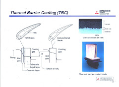
The 501G is a cold-end drive machine with 17 stages of axial-flow compressor resulting in a 19:1 pressure ratio. The combustion section is of the can-annular type with 16 individual Dry Low Nox (DLN) combustors that utilizes a closed-circuit steam cooling. This results in a much higher firing temperature at approx. 1500 C. The turbine is an air-cooled, 4-stage reaction type turbine. The first and second stage vanes and blades are TBC (Thermal Barrier Coating)-coated to reduce base metal temperatures to an acceptable level.
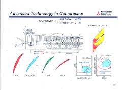
Compress0r
The 501G utilizes a 17-stage axial flow compressor capable of producing a pessure of ratio of 19:1. It has a Varaible Inlet Guide Vane which allows a constant exhaust temperature at all loads and controls surge during run-up and coast-down. Stages 1-3 utilizes a Multiple Circular Arc (MCA) profile on the blade and a Controlled Diffusion Arc (CDA) airfoil on the nozzle while Stages 4-7 fully utilize a CDA profile on blades and nozzles. The remaining stages utlize the NACA65C design. The flow path of the compressor decraeses in cross-sectional area towards the discharge. This allows a uniform axial velocity as the air is compressed. The compression process increases the temperature and pressure of the air. At compressor discharge, the temperature is at the range of 400 C -450 C. Air bleeds are also provided for surge control and cooling of hot gas path parts. Bleeds are at the 6th (Low Pressure / LP) and 11th (Intermediate Pressure / IP) stages. High pressure bleed is taken directly from the discharge (17th stage).
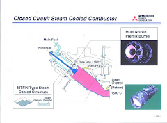
Combustor
The combustor is of the dry-low NOx type (DLN) having a dual fuel capability, either natural gas or distillate fuels. Multiple nozzles supply pre-mixed fuel for lean burn combustion. The transition piece / liner utilizes a unique cooling scheme to acheive a firing temperature of 1500 C. Closed-circuit steam cooling is used to cool the liner. Steam is extracted from the IP economizer and is circulated in the liner reheating of the steam at the same time prior to admission in the IP section of the steam turbine. Such technique improves thermal efficiency and power output.
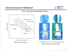
Turbine
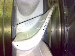
The turbine is a 4-stage axial-flow reaction type. It utilizes a Directionally Solidified (DS) blade material, which has improvements in creep and fatigue strength over Equi-axed blades. Advanced air-cooling is used coupled with thermal barrier coatings on the 1st and 2nd stage blade. This allows lower base metal temperature, permitting a higher turbine creep life usage.
Subscribe to:
Posts (Atom)